
CC104控制器
CC104 门禁控制器使用手册:涵盖产品概述、外观及接口、控锁端子、辅助输入输出、控制箱安装固定、控制板接线示意图与注意事项。

前言
感谢使用提供的CC104门禁控制器。认真阅读本文档,可以帮助您了解此设备功能、特点、以及快速掌握设备的接线、安装方法。
产品简介CC104门禁控制器是一款针对部署智能门禁系统所需的一款四门控制器,结合微光485读头和门禁云平台,可以实现门禁智能管理,拥有人员管理、访客管理、远程开门、流量监测等一系列功能。集成防拆与火警接口,使得门禁场景更加安全。此外,设备对外开发协议接口,用户可根据自身情况做对接开发。适用于银行、宾馆、写字楼、智能小区或工厂等场景。
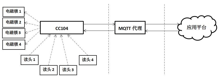
产品参数 通讯方式:TCP/IP、udp、mqtt、RS485 配套机箱尺寸(厘米):24914037 配套电源:12VDC 10A 读卡器输入格式:RS485 115200 BAUD 可接读卡器数量:四对 可控制门输出:四组 使用环境温度:-20 至 70摄氏度 用户注册卡数量:10W 记录脱机存储数量:10W 数据掉电保护:高速闪存设计,永不丢失。
应用场景示意图
外观及接口
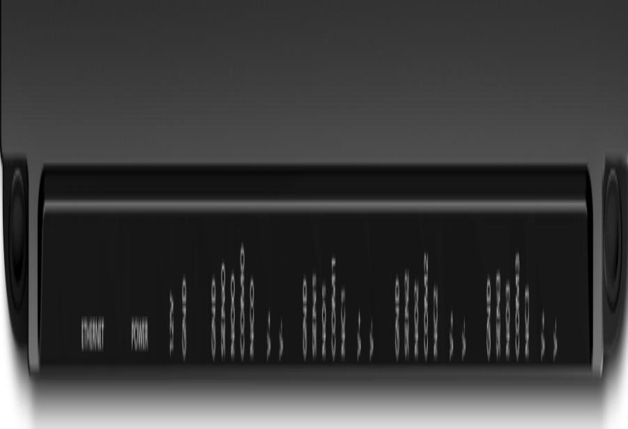
CC104 外观图
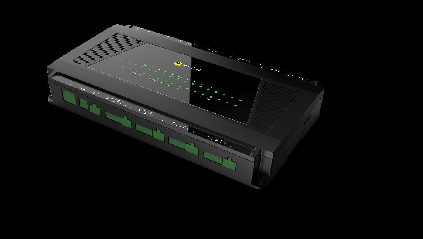
端口说明出门按钮#1两个辅助输入出门按钮#2出门按钮#3出门按钮#4外接读头#1外接读头#2外接读头#3外接读头#4四路辅助输出网线接口电源接口#1电源接口#2四路控锁端 端口说明列表端口序号 定义 说明 网线口 连接网线 2 电源接口#1 连接电源适配器(电源 1 与电源 2 任选其一)3 电源接口#2 连接外部 12V 电源(电源 1 与电源 2 任选其一)
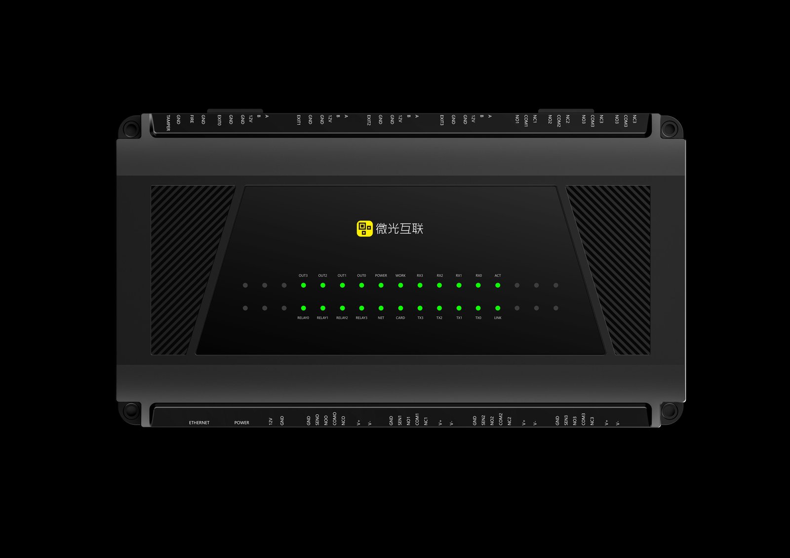
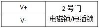
四路控锁端
GND 门磁信号输入端SENNO继电器输出端COMNCV+ 电磁锁电源V-
四路辅助输出(预留)
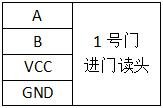
NO 继电器常开端COM 继电器公共端NC 继电器常闭端 四路外接读头 A 485AB 485B12V 12V 输出GND 电源地
两路辅助输入
GND 火警输入FIREGND 防拆输入TAMPER 门磁 GND 连接锁头门磁检测端(没有则不 接)SEN 继电器 NO 常开端COM 公共端NC 常闭端
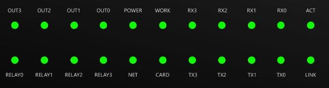
控制箱指示灯含义指示灯 定义 说明OUT(0-3) 辅助继电器输出指示灯(黄色) 亮黄灯:有效输出灭灯:无输出POWER 电源指示灯(红色) 亮红灯:上电灭灯:没电WORK 工作指示灯(绿色) 正常模式:500ms 间隔闪烁禁用模式:1500ms 间隔闪烁RX(0-3) 485 接收信号灯(黄色) 有信号时闪烁TX(0-3) 485 输出信号灯(绿色) 有信号时闪烁ACT 数据灯(黄色) 常亮:PHY 未上电时闪烁:数据收发LINK 网线灯(黄色) 常亮:网线连接灭:网线未连接CARD 刷卡指示灯(黄色) 预留NET 网络灯(黄色)灯灭:未联网 秒间隔闪烁:已连接 MQTT RELAY(0-3) 读头(0-3)对应的继电器灯(绿色) 灯亮:继电器动作
控制箱安装固定
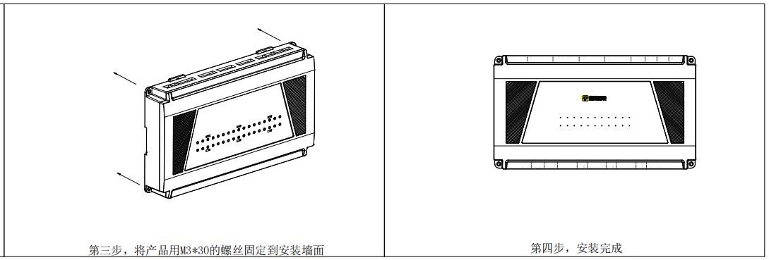
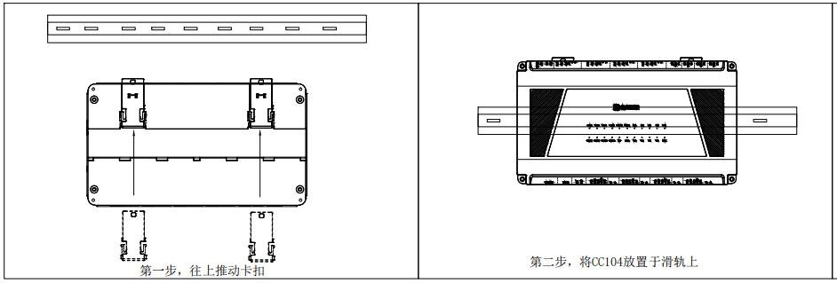
CC104控制器有两种安装方式,可根据实际场景,任选其一进行安装。
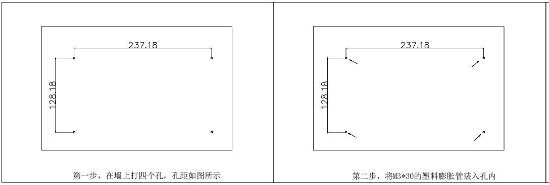
墙壁安装示意图
滑轨安装示意图
控制板接线示意图
接线注意事项 安装前,请关闭外部电路(为系统供电),包括门锁,安装完成之前,请勿通电。 设备接通电源之前,请确认电源输出电压在指定电压范围内。 所有接线端子的裸露部分强烈建议不要超过 4mm,可以使用专业的卡线工具,以防过长的裸线意外接触,而引起短路和通讯故障。 不要带电拔插接线端子。 不要将控制器和其他大电流设备接在同一供电插座上。 推荐使用手册指定规格的线材连接设备。 供电方面:电源接口1 与电源接口2 可任选其一进行供电。
双门双控接线NC3COM3NO3NC2COM2NO2NC1COM1NO1NC0COM0NO0AB12VGNDAB12VGNDAB12VGNDAB12VGNDGNDFIREGNDTAMPER485A
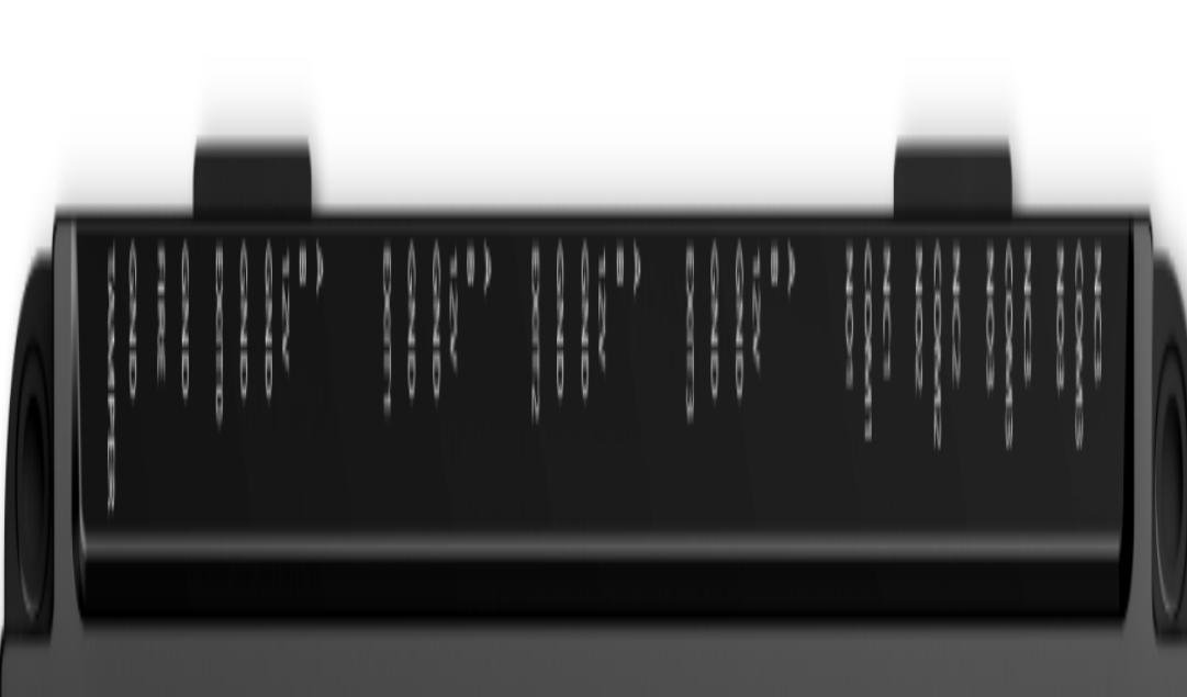
Video Tutorials
CC104 产品演示
Watch videoFAQ
How can I get the latest firmware for this product?
Firmware and upgrade packages require submitting your company information for approval; once approved, a download link will be sent. You can also upgrade online from the device backend.
The manual does not match the actual device?
Always refer to the device nameplate label and the latest version of the manual. If you have questions, contact Koodle technical support for assistance.